
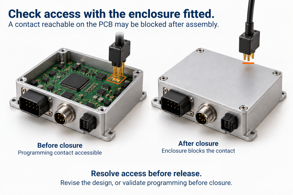
A programming contact hidden by an enclosure can turn a small layout decision into a fixture change, an extra assembly step or a reopened release plan. For an OEM preparing to scale production, the timing of that discovery matters.
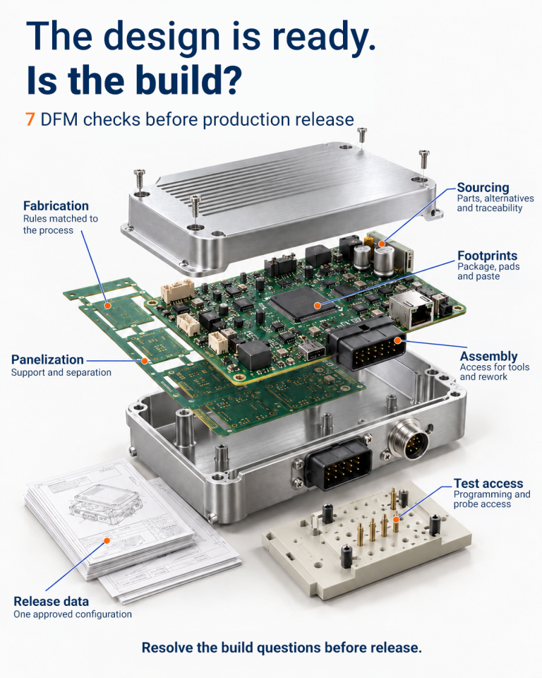
A useful DFM review connects a design finding to the decision it creates. What must change before components or tooling are ordered? What can a controlled pilot verify? Who can accept the remaining limitations, and for which build? These seven checks help product and engineering teams answer those questions before production release.
What DFM means in electronics
Design for Manufacturability (DFM), also called Design for Manufacturing, evaluates a design against the capabilities and constraints of the intended manufacturing process. In electronics, this includes PCB fabrication and assembly.
The checklist also covers sourcing, release data and Design for Testability (DFT), which addresses test access and verification. These have distinct responsibilities, but their decisions affect the same production release.
Set the release priorities first
Define the review context: design revision, intended volume, build stage, schedule, acceptance requirements and applicable standards. Then assign each finding a release decision.
Release decision | When it applies | Evidence needed |
Resolve before volume release | An unapproved substitute or conflicting build revision prevents an authorized build | Approved disposition and corrected release files |
Verify in a controlled pilot | A process assumption needs evidence from the planned build | Authorized pilot scope, test method, pass criteria and owner |
Accept for a defined build | A known limitation fits the agreed build requirements | Rationale, approver, affected quantity or revision and review trigger |
Maintain findings register that connects each observation to its production consequence, required action, and owner. Give each action a due date. Authorize the pilot’s scope before building and defer only the questions that it can answer. Revisit accepted conditions when the quantity, configuration, or process changes.
1 Match fabrication rules to the intended process
Confirm the stack-up, materials, copper features, hole structures and tolerances with the intended fabricator. A CAD design-rule check evaluates the rules configured in it; those rules need to reflect the process that will build the board.
Identify features that need special processing or validation. Decide whether their functional benefit justifies that requirement before releasing the PCB order. A later stack-up or hole change can reopen fabrication data and related validation work.
Close this check with agreed fabrication requirements and a documented decision on each unresolved query.
2 Review the footprint and solder process together
Review the land pattern, solder-mask openings, and paste apertures for the specific package and assembly process. Where specified, use IPC-7351B land-pattern guidance and confirm the package of geometry and process tolerances with the assembler.
Agree footprint and paste changes before approving the stencil. A late correction may require replacement tooling or another PCB revision. Define which process assumptions the pilot will verify and how the joints will be assessed.
Close this check with approved footprints and paste data, plus defined pilot checks and acceptance criteria.
3 Protect access for assembly and rework
Check component placement, connector mating, screw access and rework with the enclosure and neighboring hardware in place. Allow for inspection against the agreed IPC-A-610 acceptance criteria, including solder-joint assessment, and for the tools needed for rework.
A connector may fit the PCB while leaving insufficient room to attach its cable. Resolving this through an extra manual step creates a recurring assembly task. Compare that effort at the intended volume with the cost and schedule effect of changing the layout or enclosure.
Close this check with agreed keep-out areas and a verified assembly sequence.
4 Decide how the board will be handled and separated
Panelization supports board handling and provides space for tooling holes and fiducials. Review the panel against applicable IPC-2221 design requirements and the manufacturer’s process constraints.
Confirm breakaway-tab or “mouse-bite” geometry, copper clearances and nearby component placement with the manufacturer. IPC-7351B includes breakaway-pattern guidance where specified. Verify stable handling and separation of the populated assembly; a late change can affect the panel, stencil or support tooling.
Close this check with an approved panel drawing and an agreed handling and depanelization approach.
5 Review the BOM for production use
The bill of materials (BOM) should identify exact orderable parts, approved alternatives, and substitution restrictions. Check availability separately from lifecycle status; an active device is not a delivery commitment. Flag obsolete parts and those not recommended for new designs (NRND) before procurement.
Assess alternatives against electrical, package, thermal and application requirements, including any PCB changes or revalidation. Address counterfeit risk through authorized sourcing, traceability and controls for suspect parts. Approve both the part and its source before committing inventory.
Close this check with a released BOM, approved alternatives, sourcing decisions, and traceability requirements.
6 Define test access before layout release
Identify what must be programmed and verified, the proposed test methods and the fixture or software requirements. Check probe access and clearances where physical contacts are needed. Decide which operations occur before enclosure assembly, and which verify the finished unit.
Missing access can require a PCB revision or a different test sequence. Aim for 90%+ coverage against an agreed fault model, with test methods, exclusions and critical-function checks documented. Treat this as a project target, not proof that every failure mode is covered. Evaluate test time and fault diagnosis and approve remaining coverage gaps before release.
Close this check with an agreed test strategy, documented coverage, access requirements, acceptance criteria and owners for open fixture or software work.
7 Release a consistent manufacturing data set
Reconcile the fabrication data, assembly drawings, BOM, and placement files. Confirm reference designators, position, rotation and board side against the released configuration. Specify the applicable IPC J-STD-001 requirements, IPC-A-610 acceptance class, and revisions in the release package.
Set placement tolerances for the actual package and process. Include firmware, programming instructions, test procedures and enclosure drawings, with fitted and unfitted variants identified. When DFM changes the design, update every affected output before authorizing the build.
Close this check with one authorized release package, a confirmed configuration, and a defined change-approval route.
An illustrative release decision
Finding: a programming contact becomes inaccessible after enclosure assembly. Moving it could preserve access but require a PCB revision. Programming before enclosure closure could avoid that revision while changing the assembly sequence and verification steps.
Decision: compare both options against service requirements, intended volume and the release schedule. If programming before closure meets the requirements, define how firmware identity will be controlled and how the finished unit will be verified. Authorize a pilot to check the revised sequence.
Closure: record the approved method, update the affected instructions, and use pilot evidence to decide whether it is ready for the planned production quantity.
Prepare your design for production with Aimtron
The programming example shows why PCB layout, testing, and box build need to be reviewed together. Aimtron’s capabilities span product design, PCB assembly, custom test fixtures and electromechanical box builds.
For a design release, manufacturing transfer or higher-volume build, start with the product stage, target quantity and launch window. Share the current BOM, fabrication data, assembly and placement files, together with relevant test and enclosure requirements.
Agree on the review of scope and outputs: prioritized findings, proposed actions, owners and the evidence needed to close each item. The aim is to identify what must be resolved before the next manufacturing commitment.